Table of contents:
Foreword
1. Specific features of large interceptor sewers
1.1 Materials and profile shapes
1.2 Assessment of condition
1.2.1 Basis for assessing the condition
1.2.2 Historic research, surveying and monitoring
1.2.3 Structural inspections
1.2.4 Soil parameters
1.2.5 Results of the condition survey for the calculation and dimensioning of the liner
2. Rehabilitation procedure (suitability for large profiles in condition III)
2.1 Pipe lining method
2.2 Single pipe lining (short pipe lining)
2.3 PVC spiral wound method with filling the annular gap with load-bearing grout
2.4 Shotcrete with satically effective reinforcement
3. Static dimensioning of rehabilitation systems
3.1 Application of the partial safety concept
3.2 Static modeling, imperfection approaches, verifications
4. Conclusions
Literature
Authors: Dr.-Ing. Dietmar Beckmann (S&P Consult GmbH), Dr.-Ing. Heinz Doll (TÜV Rheinland LGA Bautechnik GmbH), Dipl.-Ing. Vladimir Lacmanović (IngSoft GmbH)
Would you like the PDF version of this article? Please feel free to contact us!
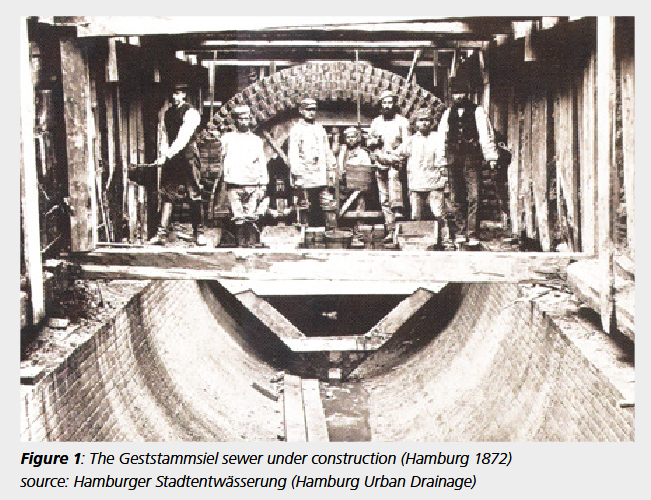
Rehabilitation of large profiles lacking long-term stability
The large wastewater collectors, which are mainly laid under public roads, have often been in operation for over 100 years. They are made of masonry or tamped concrete and often show such serious damage that their long-term stability no longer appears to be guaranteed. As an alternative to renewal, various renovation methods are also available for large sections, which offer significant advantages in terms of investment costs, environmental protection and urban pollution. Depending on the process, the extension of the service life achieved can be equivalent to that of a renewal. The prerequisite is a detailed investigation of the actual stability or residual load-bearing capacity of the existing sewer and a needs-based selection and dimensioning of the rehabilitation method. The new worksheet DWA-A 143-2 provides a good basis for the necessary structural calculations, which are described in detail in Part 2, 3R Issue 3/2016.
1. Specific features of large interceptor sewers
1.1 Materials and profile shapes
In accordance with the requirements and constructional possibilities valid at the beginning of the last century, the channels were often built with brickwork, whereby natural stone was occasionally used, but mainly man-made bricks (fired solid bricks/clinker bricks). Depending on the dimensions and the loads at the time, the masonry shells were constructed in one, two or even three layers, with the wall thickness often changing within the cross-section. In addition, channels were also made of tamped concrete at an early stage, although the strength of this varies greatly today. Reinforcement in the concrete is rare and usually does not meet today's requirements for reinforced concrete.
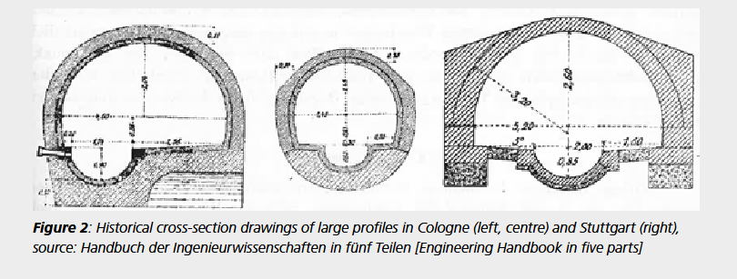
The standard profile shapes with circular or egg-shaped cross-sections that predominate in smaller sewers give way to other, more operationally and statically favorable profile shapes as the size of the collectors increases. Most large profiles can be classified as either a mouth or a hood profile. However, the individual cross-sectional shapes occur in different variants, which can be specified in more detail, for example, with the attributes wide, compressed, stretched or raised. The aim of the designers and structural engineers at the time was to achieve load transfer via a compression vault, as the materials used could only absorb very limited tensile stresses. This load-bearing behavior requires an appropriate support or foundation for the arch with sufficient load-bearing capacity and rigidity of the subsoil.
In many cross-sections, the base of the sewer is designed as a separate arch, which must be regarded as statically decoupled from the main arch and (at least above the groundwater level) usually has no influence on the overall stability of the sewer. Fig. 2 shows examples of different cross-sectional shapes.
1.2 Assessment of condition
1.2.1 Basics of the assessing the condition
The condition assessment for large sections is generally based closely on the newly published worksheet DWA-A 143-2 (July 2015) [2], which regulates the structural calculation for the rehabilitation of wastewater pipes and sewers using lining and installation methods. Although this set of rules primarily relates to pipes and sewers with (smaller) circular and ovoid sections, the basic procedure for calculation and dimensioning is also adopted for large sections. For the basic classification of the stability of the sewer to be rehabilitated (referred to as old pipe in DWA-A 143-2), a distinction is made between three basic "old pipe conditions"(Fig. 3):
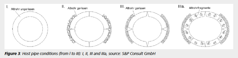
Old pipe condition I: The old pipe alone is load-bearing. In this case, the liner only has to ensure that the sewer is watertight. As the old pipe can carry all external loads on its own, the liner is only loaded by the groundwater that seeps through the leaking sewer wall and builds up an external pressure corresponding to the groundwater level.
Old pipe condition II: The old pipe is not capable of bearing loads on its own and is longitudinally cracked at four points around the circumference (crown, transom and invert). The resulting quarter shells have twisted against each other, causing the cross-section to ovalize. The clear height of the cross-section has been reduced, but the cross-section has become wider and has pressed into the ground in the transom area. The soil supports the sewer and a load-bearing system is created, consisting of the cracked old pipe and the supporting soil, the so-called old pipe-soil system. If this old pipe floor system is structurally stable with the required safety, the old pipe is in old pipe condition II. In this case, the liner only has to ensure the tightness of the sewer in the same way as in old pipe condition I. As the old pipe can carry all external loads on its own, the liner is only loaded by the groundwater that flows through the leaking sewer and builds up external pressure. In contrast to old pipe condition I, an oval preformed liner may have to be expected.
Old pipecondition III: This old pipe condition corresponds to old pipe condition II with the decisive difference that the stability of the old pipe floor system can no longer be proven. In this case, the liner not only has to bear groundwater loads, but must also participate at least partially in the absorption of all impacts such as earth loads, traffic loads and superimposed loads. Compared to old pipe conditions I and II, the effects on the liner in old pipe condition III are generally many times greater. In DWA-A 143-2, a further old pipe condition was created, which is referred to as old pipe condition IIIa, but was only included in the informative appendix of the regulations. In contrast to the existing old pipe condition III, it is assumed that the quarter shells between the joints (cracks) of the old pipe do not remain intact and break, meaning that the old pipe no longer has any supporting effect. Large sections that must be assigned to this old pipe condition IIIa can be rehabilitated in exceptional cases in consideration of special measures and are therefore not considered further below.
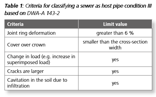
Table 1 shows the criteria defined in DWA-A 143-2 for differentiating between old pipe conditions II and III. For large profiles, the information in this table can be used at best as an initial guideline. Instead, more precise and in particular individual investigations of the cross-section are necessary and justified, as on the one hand the risk potential is significantly greater than for small pipes and on the other hand there is a high potential for savings when carrying out the rehabilitation.
1.2.2 Historic research, surveying and monitoring
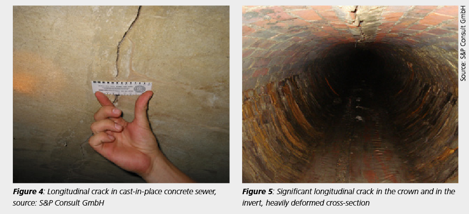
Figure 6 shows a significantly wider longitudinal crack, which already requires a short-term stability assessment. In Fig. 7, the longitudinal crack in the crown of the masonry is so pronounced that an acute danger cannot be ruled out. Immediate measures are required here, especially as the base has already opened up and the entire cross-section is considerably deformed. Initial investigations can already be carried out as part of the visual inspection (e.g. determining the reinforcement content using profometer measurements) or monitoring with plaster or crack markers can be initiated.
1.2.3 Structural inspections
Due to the large number of often regionally different cross-sectional shapes, a survey of the inner contour is part of a condition assessment in order to be able to record it with sufficient accuracy in the calculation model. The outer contour of the sewer can be determined by measuring the wall thicknesses if the historical documents do not allow sufficient conclusions to be drawn. In addition to the geometry, the strength of the materials used in the current condition is decisive for verifying the stability of the sewer. To determine the material characteristics, a sufficient number of cores are taken using a core drill with a diameter of 100 mm (for concrete) or 150 mm (for masonry). The visual inspection of the drill cores already provides initial information about the strength properties of the wall. The material parameters, which serve as input values for the structural analysis, are determined in laboratory tests.
1.2.4 Soil parameters
The stability of large profiles is determined to a large extent by the properties of the subsoil. The soil must not only provide a secure (vertical) foundation, particularly in the case of already cracked ducts, but also plays an important role in the lateral (horizontal) bedding of the system. The supporting structure does not consist exclusively of the sewer wall alone, but also of the interaction of the masonry or concrete with the surrounding subsoil. For this reason, knowledge of the soil parameters is essential for the structural analysis. In order to obtain reliable values, a subsoil laboratory or at least a geotechnical expert must be consulted. After field tests and soil sampling, the subsoil parameters relevant for the structural analysis are determined in geotechnical laboratory tests. In addition to the specific weight of all soil layers above and next to the sewer, the following two parameters of the soil at transom height can have a significant influence on the stability of the sewer:
- Friction angle j' to define the load-bearing capacity of the lateral bedding
- Stiffness modulus Es to define the stiffness of the lateral bedding.
If groundwater is present, not only its highest but also its lowest level must be known, as the groundwater situation that is decisive for the dimensioning of a liner to be dimensioned for the old pipe condition III is usually only determined when the calculation is carried out. The groundwater levels are determined by the subsoil expert.
1.2.5 Results of the condition survey for the calculation and dimensioning of the liner
The condition survey presented in the previous chapters provides the following information and input values for the structural calculation of the sewer:
- Geometry of the sewer cross-section " Old pipe condition of the sewer
- Position, width and length of statically relevant cracks
- Other damage (e.g. reduction in wall thickness due to corrosion)
- Material characteristics of the sewer wall
- Soil characteristics
This allows a static model to be created on the basis of the finite element method. The result is a fairly reliable statement about the stability of the sewer in its unrenovated state. After a sensitivity analysis with regard to the individual input parameters, the classification into the old pipe condition II or III is carried out, thus creating the most important basis for the calculation and dimensioning of the liner.
2. Rehabilitation procedure (suitability for large profiles in condition III)
The focus is on renovation methods. Renovation processes are measures to improve the current functionality of wastewater pipes and sewers while fully or partially incorporating their original substance. In principle, renovation processes include coating and lining processes. For the structural upgrading of large, accessible collectors, the only methods currently used are
- the pipe lining method (up to approx. DN 2000),
- single pipe lining,
- the spiral pipe method with load-bearing annular space filling and
- the shotcrete method with statically effective reinforcement.
2.1 Tube lining process
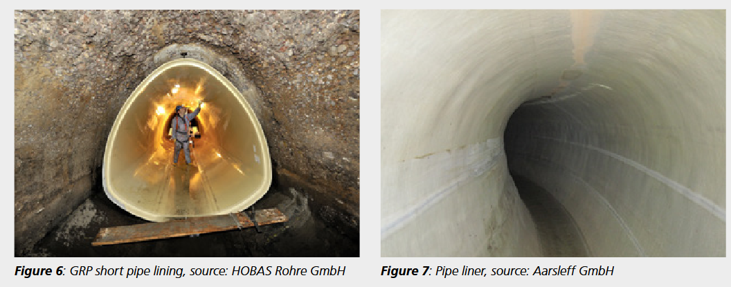
Overall, the pipe lining method (accessible and non-accessible areas) is currently the most frequently used renovation method. In the area of large profile renovation, however, the upper nominal width limit is currently around DN 2000. Furthermore, the applicability must be checked depending on the profile shape (especially for inverted channels). The basic concept of all hose lining methods consists of inserting a hose impregnated with reaction resin, which is made up to the length and internal dimensions of the old pipe, through the manholes (if necessary with the cone removed) into the sewer.
In the sewer, the hose is pressed against the pipe wall by air or water pressure and, depending on the process, cured to form a liner with defined rigidity and strength. The requirements for a renovated sewer are the same as those for a new sewer. The renovated sewer must be tight and reliable, have sufficient hydraulic capacity, be resistant to abrasion and high-pressure cleaning and be able to permanently absorb the static effects. The differences between the individual pipe lining methods lie mainly in the materials used (base material GRP or synthetic fiber, resins), the installation (pipe installation method) and the curing method (hot water, light, cold curing).
2.2 Single pipe lining (short pipe lining)
In single pipe lining, factory-made pipes are inserted into the section to be rehabilitated via excavation pits. The individual pipes are usually connected to each other in the section to be rehabilitated. The resulting annular space is then filled. The method can be used for all old pipe conditions and for most cross-sectional shapes (including, for example, a mouth profile with invert channel). There may be restrictions with regard to applicability in the case of very soft soils in the bedding zone and in the case of very large collectors (transportation problem of the prefabricated pipes). The sewer and the bedding must be sufficiently stable, at least temporarily (work in the sewer).
The pipe section to be rehabilitated must be free of drainage obstacles and must be taken out of service for the duration of the work. Pre-sealing is required in the event of heavy groundwater infiltration. The process is not tied to any specific pipe materials. Pipes made of GRP are usually used, as they are largely adaptable to the different cross-sectional shapes. The pipe connections are realized with sockets or slip-on couplings, as bonded connections or also as overlaminate connections (possibly combinations). The pipes are moved into the pipe section to be rehabilitated using special transport equipment, so-called trolleys, on which the pipes are placed. The pipes are then fixed in place with spacers and secured against the forces acting during the filling of the annular space (especially buoyancy). This work is carried out by hand, e.g. by backfilling with quick-setting mortar or softwood wedges, using special support saddles or spacers. Among other things, the annular space filling should achieve the following:
- Securing the position of the lining pipe
- Creation of a defined bedding of the lining pipe
- Avoidance of water transport through the annular space
- Avoidance of soil ingress due to defects in the
- old pipe
- Avoidance of gas accumulation in the annular space
- Uniform transfer of external loads.
Other advantages associated with filling the annular space are
- Prevention of the collapse of the defective sewer
- Buoyancy protection of the pipeline
- Compensation for different temperature-related changes in length
- Filling of existing cavities, even outside the sewer.
The annular space can be filled in two ways:
- Unpressurized backfilling using the natural gradient of the sewer bed (backfilling from the high point)
- Backfilling under pressure (backfilling from the low point).
As part of large profile rehabilitation, the annular space is usually backfilled in several layers. In addition to the final tests, the final work includes
- Shaft connection
- Adaptation of the inliner to the manhole channel
- Restoration of the integration of connecting sewers and house connections
The SPR coiled pipe profile is fed through a standard shaft to the coiling machine. The dismountable coiling machine, which is also installed via a shaft, forms the SPR profile into a plastic liner pipe, which serves both as formwork during installation and later as internal protection for the mineral pipe. During the winding process, mineral spacers are used to ensure the required wall thickness of the subsequent 'pipe in pipe'. To ensure that the SPR lining pipe can absorb the external pressure of the backfill material during the annular space filling, adjustable and braceable support frames are installed as a bracing system for larger cross-sections. The defined annular space between the SPR liner and the old pipe is backfilled using a highly flowable and high-strength backfilling material. The filling creates a mineral 'pipe within a pipe', which has a high level of rigidity and is used solely for load transfer. The PVC-U lining pipe is not load-bearing, but protects the load-bearing pipe against chemical and mechanical attack from the inside.
2.3 PVC spiral wound method with filling the annular gap with load-bearing grout
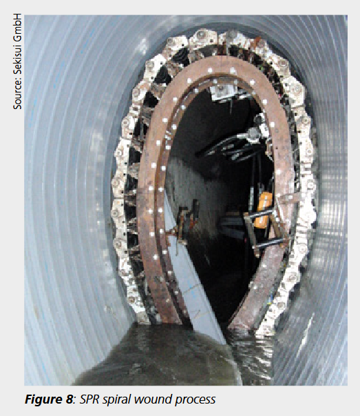
The only representative of the coiled pipe method with supporting annular space filling is the 'Sewage Pipe Renewal' method or SPR method, which originated in Japan. It is characterized by the winding of a lining pipe made of PVC web profiles with steel reinforcement within the rehabilitation section. The PVC web profile is unwound from a roll and fed via a manhole to a self-propelled winding machine, which moves along a closed frame adapted to the contour of the sewer to be lined. The SPR process can be used for the rehabilitation of gravity sewers with nominal diameters of DN 800 to DN 5500. The liner can be adapted to many old pipe cross-sections, such as egg-shaped, rectangular or mouth-shaped profiles. Curved pipe sections can also be rehabilitated if their curve radius corresponds to five times the nominal width. Rehabilitation is also possible with controlled dry weather flow. House connection pipes can remain completely in operation. The process requires little space on the construction site.
The SPR coiled pipe profile is fed to the coiling machine through a standard shaft. The demountable coiling machine, which is also installed via a shaft, forms the SPR profile into a plastic liner pipe, which serves both as formwork during installation and later as internal protection for the mineral pipe. During the winding process, mineral spacers are used to ensure the required wall thickness of the subsequent 'pipe in pipe'. To ensure that the SPR lining pipe can absorb the external pressure of the backfill material during the annular space filling, adjustable and braceable support frames are installed as a bracing system for larger cross-sections. The defined annular space between the SPR liner and the old pipe is backfilled using a highly flowable and high-strength backfilling material. The filling creates a mineral 'pipe within a pipe', which has a high level of rigidity and is used solely for load transfer. The PVC-U lining pipe is not load-bearing, but protects the load-bearing pipe against chemical and mechanical attack from the inside.
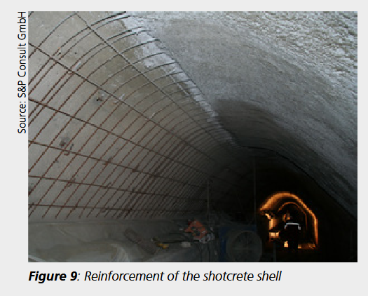
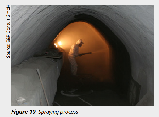
2.4 Shotcrete with statically effective reinforcement
According to DIN 18551, shotcrete is a "concrete that is conveyed to the installation site in a closed, pressure-resistant hose or pipe and applied there by spraying and compacted in the process". In principle, shotcrete does not differ in composition from conventional in-situ concrete. The difference lies in the conveying, placing and compacting, i.e. in the processing, which is combined in a single operation, the spraying. Formwork and vibrators are not required. Shotcrete with a thickness greater than 5 cm, which is usually the case when renovating large profiles, must be reinforced. The reinforcement can be laid in one or two layers. With two-layer reinforcement, the spraying process must first be carried out up to the first reinforcement layer and then over the second reinforcement layer. The reinforcement is connected to the old channel using anchors. In addition to the compaction, the high application energy released during the spraying process also ensures a good bond to the substrate.
Depending on the type of initial mixture, a general distinction is made between dry spraying and wet spraying. In the dry spraying process, the ready-mix, consisting of cement, aggregate and, if necessary, powdered additives, is fed dry into the delivery line and conveyed pneumatically in a thin stream to the spray nozzle, where the admixture water, possibly with liquid concrete admixtures, is mixed in. In the wet spraying process, the preparation mixture, consisting of cement, aggregate, admixture water and any additives, is fed to the delivery line in wet form and conveyed either in a thin stream or in a dense stream.
In practice, the dry spraying process predominates, as it is less problematic in terms of storing the initial mixture and in the event of work interruptions. When the mixture leaves the spray nozzle, it has a high kinetic energy, which causes the shotcrete or spray mortar to compact when it hits the substrate. Due to this high energy with which the mixture hits the substrate, part of it bounces back again. This so-called rebound consists mainly of coarse aggregate, which is coated with cement paste or mortar, so that the composition of the sprayed concrete differs from that of the preparation mixture. The cement content of this mixture must therefore be determined in such a way that the hardened concrete achieves the required properties. At the start of spraying, a larger rebound quantity is produced, as a plastic cushion must first be formed on the substrate to absorb the coarser aggregates. The rebound quantity depends on numerous influencing parameters, such as
- Composition of the preparation mixture,
- spraying method,
- Local conditions on the application surface,
- nozzle guidance,
- spray direction,
- spray angle,
- nozzle spacing,
- working pressure,
- delivery technology or
- impact velocity
and amounts to approx. 20 to 30 %. If all influencing parameters are set optimally, the rebound percentage in the dry spraying process can be reduced to approx. 15 to 20 % when spraying on a vertical application surface. The rebound percentage in the wet spraying process in the thin stream is approx. 12 to 14 % and in the wet spraying process in the dense stream approx. 6 to 7 %. It is therefore the most economically favorable process when considering only process engineering parameters. Part 2 of this technical article (3R issue 3-2016) presents methods for the static calculation and dimensioning of the rehabilitation methods.
3. Static dimensioning of rehabilitation systems
The type and scope of the static dimensioning of rehabilitation systems that are to be used to upgrade the accessible collectors under consideration here are largely dependent on the condition of the old pipe, i.e. the residual load-bearing capacity of the existing pipe. Since July 2015, DWA-A 143-2, the successor standard to ATV-M 127-2, has formed an essential basis for the static verification of lining and installation methods. In the following, the changes and additions made to DWA-A 143-2, insofar as they relate to the safety concept and the imperfections to be applied, are presented in comparison to ATV-M 127-2. Finally, examples of static modeling are given and the effects of the new normative regulations are shown.
3.1 Application of the partial safety concept
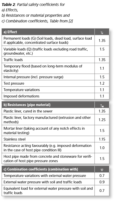
One of the most significant innovations in DWA-A 143-2 compared to ATV-M 127-2 is the transition from the global safety concept to the partial safety concept. Previously, static verification was carried out using characteristic material values (strengths σBr,k and moduli of elasticity Ek, e.g. defined in DIBt approval). The index "k" describes characteristic material values. The stresses calculated under the effect of the service load (σk) had to have a sufficient safety margin to the material strength (e.g. for old pipe condition II: erf.ϒ = 2.0, for old pipe condition III: erf.ϒ = 1.5). Furthermore, proof of deformation and stability had to be fulfilled. Tables 2a and 2b contain the partial safety factors gF and gM specified separately for actions (loads) and resistances (material properties) in DWA-A 143-2 and Table 2c contains the combination coefficients ψ that can be applied when considering load combinations (interaction verifications).
As part of the static calculation in accordance with DWA-A 143-2, a geometrically non-linear calculation of the problem is carried out with an iterative load increase up to gF times the service load, whereby the material parameters reduced by the partial safety factor gM (Ed = Ek/gM, σBr,d = σBr,k/gM) are to be applied. The index "d" describes the design values of the material. The stresses σd determined under ϒF-fold load are therefore compared with the strengths σBr,d reduced by gM. This means that loads (in the stress analysis σd/σBr,d) are determined which may assume a maximum value of 1.0 (100 % load).
As the stress analysis is carried out non-linearly under ϒF-fold load (action), the stability analysis is included in it. The deformation check is still carried out using characteristic material values (Ek) under service load. Some consequences resulting from the partial safety factors listed in Table 1 and from the application of the partial safety factor concept are shown below:

If the product of the partial safeties ϒF - ϒM is considered as an approximation for the global safety ϒ, the comparison of the safeties listed in Table 3 results for rehabilitation methods used in the area of large section rehabilitation. It is clear that both sets of regulations DWA-A 143-2 and ATV-M 127-2 require a virtually identical level of safety (2.0 ≈ 2.025) for pipe liner rehabilitation in old pipe condition II. This is of particular importance as the design tables of DWA-M 144-3 remain valid despite the change in the design basis. In this regard, it should be noted that comparative calculations based on the draft of DWA-A 143-2 were also carried out as part of the structural review of the design tables.
A further prerequisite for the applicability of the tables is, of course, still compliance with the assumed material parameters and imperfection approaches. The comparison of the safety levels of the two sets of rules listed in Table 2 also shows that for insulated GRP pipes, due to the partial safety factor ϒM = 1.25 for old pipe condition II, there is a drop in safety to erf.ϒ ≈ 1.88 (previously erf.ϒ = 2.0). If old pipe condition III, i.e. earth and road traffic loads, is to be taken into account, DWA-A 143-2 results in an increase in the required safety compared to ATV-M 127-2 in all cases considered.
In connection with fluctuating groundwater levels, the question occasionally arose in the past as to how to deal with the load case of flooding. The design of a plastic liner using the long-term material parameters and a required global safety factor of ϒ = 2.0 (ARZ II) appeared to be too conservative and also too uneconomical. DWA-A 143-2 offers an option for verification by specifying a partial safety factor of ϒF = 1.1. The prerequisite for the application of this coefficient is the consideration of long-term material parameters (modulus of elasticity and strength) in the structural analysis. With the aforementioned approximation (ϒ ≈ ϒF - ϒM), this results in a safety factor of approx. ϒF - ϒM = 1.1 - 1.25 = 1.375 (<1.5 - 1.25 = 1.88).
The short-term nature of the flood event is therefore taken into account by reducing the safety level compared to the case of a long-term external water pressure load. This procedure is therefore only permissible for materials with a load-deformation behavior that depends on the loading time, i.e. for plastics. Otherwise (e.g. mortar liners, shotcrete inner shells, etc.), ϒF = 1.5 must be calculated analogously to the case of long-term external water pressure loading. It should be noted that for plastic systems it is still possible to carry out the structural analysis using the material parameters valid for the loading time of the flood event, e.g. from the creep test in combination with a partial safety factor ϒF = 1.5. For both verification options, the expected duration of action should be requested from the client or their representatives. The second verification option described above may well be decisive, e.g. for longer exposure times or for plastics that show a relatively rapid reduction in material properties (e.g. PE-HD, possibly an exceptional case).
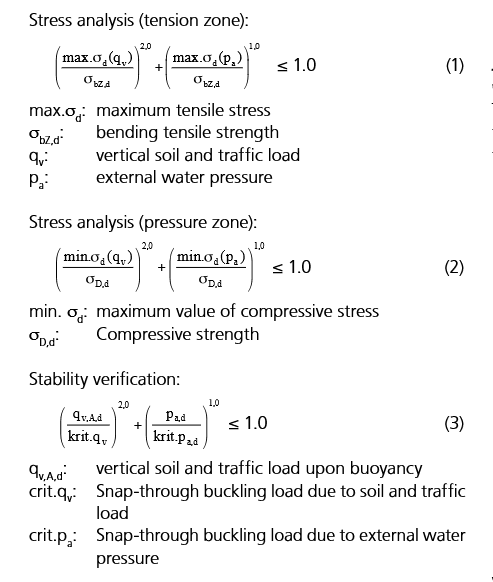
Finally, a new feature of DWA-A 143-2 is the recording of restraint stresses (ϒF = 1.1) in rehabilitation systems. They can be caused, for example, by the effects of temperature, but also by earth and traffic loads in the case of old pipe condition III. In the latter case, the cross-section of the soil-embedded system of a flexible old pipe is deformed by earth and traffic loads (due to longitudinal cracking, or due to a lack of tensile stress transmission, e.g. in masonry). This deformation acts as a forced deformation on the liner. Whether the load effect or the forced effect is dominant depends on the stiffening effect of the liner [5]. As this question cannot be answered from the outset, both cases must be taken into account in the structural analysis by applying the different partial safety factors. In addition to the static verification of individual actions, the admissibility of combinations of actions must be verified, whereby the combination coefficients ψ listed in Table 1c may be applied. The most frequently required interaction verification concerns the consideration of the simultaneous action of earth and live load (qV) and external water pressure (pa). It can be performed by applying equations (1) to (3).
The equations are already available in a similar form in ATV-M 127-2 and were merely converted to design values (index "d" in equations 1 to 3) in DWA-A 143-2. As part of the calculation, the earth load component of the vertical load may be determined taking into account the buoyancy effect; furthermore, an annular gap approach may be neglected as part of the calculation of crit.pa. A new feature of DWA-A 143-2 is the possibility of performing a calculation on the entire system, taking all actions into account. From the above explanations on the partial safety concept of DWA-A 143-2, it is clear that, particularly with ARZ III, numerous combinations of load cases arise in conjunction with different combinations of coefficients ϒF/ϒM/ψ to be applied, which must be statically analyzed [6]. This results in more calculation runs than according to ATV-M 127-2, from the results of which the stability and serviceability of the liner must be interpreted.
3.2 Static modeling, imperfection approaches, verifications
In the following, only trenchless methods that are used for the structural strengthening of large collectors are considered. The finite element method (FEM) can be used for the structural analysis of such rehabilitation systems,
- since existing collectors are often special profiles (see above) and any cross-sections can be taken into account in the static modeling with the help of the FEM,
- since a model created for the as-built assessment (old pipe classification) can continue to be used by adding the component of the rehabilitation system,
- because in this way it is relatively unproblematic to statically examine different rehabilitation variants and evaluate their expected success,
- as it is relatively easy to take into account soil stratification, which in the case of large profiles can also change in the area of the collector height
and - all loads can be considered in one calculation, which offers advantages when performing the interaction verification (see above).
The principles of static modeling have ultimately not changed with the publication of DWA-A 143-2. The static model to be applied is essentially dependent on the old pipe condition I, II, III or IIIa of the existing collector and the load effect. In the case of old pipe condition II, the liner is primarily stressed by the effect of external water pressure. In accordance with DWA-A 143-2 and ATV-M 127-2, the static calculation is carried out using the system of a liner cross-section that is quasi-rigidly embedded in the old pipe. While the standard software available primarily enables the calculation of circular and regular profiles, the use of FEM allows a wide variety of cross-sectional shapes (e.g. jaw profiles, profiles with channels, etc.) to be taken into account in the static modeling. The liner can be modeled using a wide variety of element types (beam, slice, shell or solid elements).
The bedding of the liner in the old pipe-soil system is simulated, for example, by means of support using compression springs distributed over the outer wall of the liner or by defining a corresponding contact condition. In addition to the liner thickness, the modulus of elasticity is the main stiffness property of the liner. According to DWA-A 143-2, the design value Ed is to be used. The external water pressure is applied to the outer wall of the liner as a linear or surface load and iteratively increased up to ϒF times the service load as part of a geometrically non-linear calculation. Stress and stability verification must be carried out taking into account the design values, and compliance with the permissible liner deformations must also be verified taking into account the characteristic values.
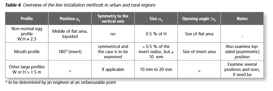
As this is a stability problem, imperfections (gap formation, local pre-deformation and joint ring pre-deformation) must be taken into account in the geometric modeling of the liner. It is very positive that the information on imperfection approaches has been significantly expanded in DWA-A 143-2. In particular, other methods (single pipe lining, spiral pipe lining, dimpled hose method) as well as other cross-sectional shapes in addition to circular and regular pipe profiles are addressed. Large collectors in particular often have special profile shapes. According to DWA-A 143-2, in these cases a joint ring pre-deformation wGr,v of the apex towards the inside must be taken into account for spiral pipe and dimpled hose methods. In the case of insulated methods, wGr,v is not applied. The local imperfection is to be applied at the location of the expected buckling failure. Known damage patterns or test results can provide indications of the decisive buckling area (e.g. for circular profiles in the invert area, for egg-shaped profiles in the transom area). Table 3 from DWA-A 143-2 provides information on the local pre-deformation to be applied for special cross-section shapes (applies in particular to large section rehabilitation).
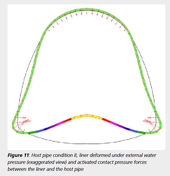
Figure 11 shows an example of a liner deformed exclusively under external water pressure in a mouth-shaped old pipe (exaggerated representation). The rather flat curved invert tends to deflect and activates high support forces in the corners. The gap between the old pipe and the liner as well as an unfavorable local pre-deformation of the invert have a correspondingly large influence on the stability. Due to the high sensitivity with regard to the corresponding imperfections "local pre-deformation" and "gap", the approaches in the structural analysis must be carefully determined and implemented on the safe side. If old pipe condition III is present, the liner, old pipe cross-section and surrounding subsoil are taken into account in the structural modeling. Using the FEM, the components mentioned can be taken into account with their actual geometry (pipe cross-sections) or stratification (soil). The discretization is usually carried out as a plane FE model or as a three-dimensional shell with the help of shell or volume elements. Contact conditions (pure compressive stress transfer) must be taken into account in the transitions between the liner and the old pipe or between the old pipe and the ground. The old pipe cross-section is mapped as a joint chain. While four overload-related longitudinal cracks (joints) in the crown, invert and transoms must be taken into account for circular profiles in ARZ III, the locations of longitudinal cracks in special profiles are not necessarily known from the outset. If necessary, a calculation should first be carried out as a rigid old pipe cross-section. Finally, the joint is attached at the points where the maximum tensile stresses occur.
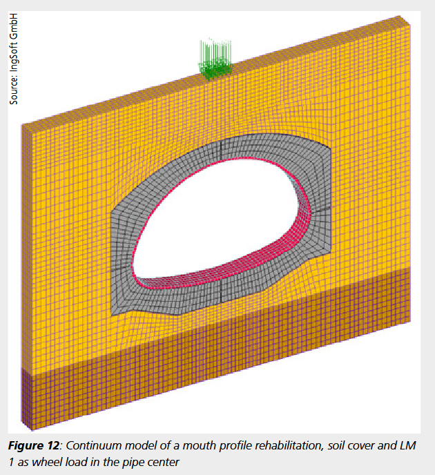
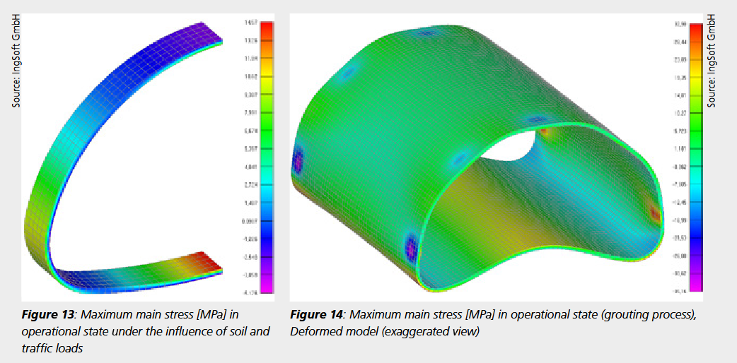
Figure 12 shows the modeling of a mouth-shaped GRP pipe in the old pipe condition III. A wheel load was applied as the live load due to the low cover height. Dead weight loads are taken into account by assigning the material-specific weights to the elements, live loads are surface loads on the model surface. The geometrically non-linear calculation is carried out using the design values and the ϒF-fold loads. Stress, stability and deformation verifications must be performed. Figure 13 shows an example of the course of the maximum principal stresses under the effect of the earth and live loads. One half of the model was calculated and shown, as the problem is symmetrical. Figure 14 shows the course of the maximum principal stresses of a GRP masonry profile in the as-built state. The local stress peaks result from wedging at the support points, which have an area of approx. 10 x 10 cm. To give a better impression, the deformed model is shown with an exaggerated deformation.
4. Conclusions
The DWA-A 143-2 worksheet published in July 2015 provides a good basis for the preparation of structural calculations as part of the renovation of large profiles. However, the large dimensions and the associated relatively high costs for carrying out the rehabilitation justify a more precise and therefore more complex structural assessment and calculation, as on the one hand there is a high risk potential for the public road space and on the other hand there is great potential for savings. For this reason, the determination of the "old pipe condition" should not be based solely on a visual inspection, but on an extended condition assessment of the sewer, which ideally includes the following investigations:
Inspection of as-built plans and, if necessary, historical documents
Inspection of the sewer and documentation of statically relevant damage (cracks, corrosion)
Assessment of the current stability or acute risk of collapse
Creation of monitoring fields with plaster and crack marks
Determination of the geometry of the inner and outer contour of the sewer wall (measurement, determination of wall thickness)
Sampling of the sewer wall (profometer measurements, core sampling, removal of reinforcement rods if necessary)
Laboratory tests to determine the statically relevant material parameters
Soil investigations in and next to the former trench
Laboratory tests to determine the statically relevant soil parameters
The results of the extended condition survey are first used to determine the condition of the old pipe in accordance with DWA-A 143-2 and to select the renovation method. The subsequent static calculations, both for the actual condition and for the design of the liner, can generally no longer be carried out using the formulae of DWA-A 143-2, as the application limits are exceeded in many respects. Instead, a static analysis must be carried out in full compliance with the regulations using the finite element method, which requires the structural engineer to have in-depth knowledge of the numerical methods of mechanics in addition to precise knowledge of the rehabilitation methods. The corresponding structural analysis provides an optimal dimensioning of the rehabilitation method (the liner) including all necessary verifications regarding the long-term stability and serviceability of the sewer. This ensures that even large collectors can be rehabilitated as cost-effectively as possible and still remain functional over the entire planned period without endangering surface traffic.
Literature:
[1] Stein, Dietrich; Stein, Robert: Maintenance of sewer systems, 4th edition, Volume 1, Prof. Dr.-Ing. Stein&Partner GmbH, Bochum 2014
[2] Worksheet DWA-A 143-2 "Rehabilitation of drainage systems outside buildings - Part 2: Static calculation for the rehabilitation of wastewater pipes and sewers with lining and installation methods", German Association for Water, Wastewater and Waste, 2015-07
[3] ATV-M 127-2 "Structural analysis for the rehabilitation of sewers and drains using lining and installation methods", 2000-01
[4] DWA-M 144-3 "Additional technical contract conditions (ZTV) for the rehabilitation of drainage systems outside buildings - Part 3: Renovation using the pipe lining method (in-situ curing pipe lining) for sewers", 2012-11
[5] Doll, H.: "The pipe liner as a static load-bearing element in the old pipe", bi-Umwelt, special issue 03/2014
[6] Beckmann, D.; Kohler, J.: "Old pipe condition III and groundwater: Verification concept for liners in sewers that are not permanently stable", 3R, 11-12/2013