Table of Contents:
1. Fundamentals and introduction
1.1 Preface
1.2 Previous approach
1.3 Future approach
1.4 Timeline
2. Loads from two standards - a comparison
2.1 Area loads
2.2 Concentrated loads
2.3 Comparison of SLW60 and LM1
2.4 Interim result
3. Ground pressure and load propagation
3.1 Distinctions
3.2 Consideration at the single wheel
3.3 Superposition with a second wheel
3.4 Full superposition of the DIN-FB
3.5 Interim result
Author: Dipl.-Ing. Frederik Müller (IngSoft GmbH)
(This article was originally written in German and translated with DeepL)
1. Basics and introduction
1.1 Foreword
The widely used approach of equivalent area loads from road traffic for buried pipelines and manhole structures will be replaced in the foreseeable future: It will be replaced by the load models of DIN Technical Report 101 for bridges, which focuses on individual wheel loads. SLW 60 according to DIN 1072 and load model 1 according to DIN Technical Report 101 are compared. An exemplary investigation of the soil pressures as well as the load propagation for load model 1 is carried out.
1.2 Previous approach
Especially in shaft and pipeline construction, the load distribution in depth is of interest. Until now, the approach of area loads was (and still is) legitimate; these could be converted into stresses quite easily. The ATV-DVWK-A 127 [2] code of practice responsible for pipes laid in trenches is based on DIN 1072 [1] in the area of road loads.
The A 127 indicates a total area of 18 m² for the heavy load vehicle (SLW) 60 with a total load of 600 kN - this corresponds to about 60 tons. This results in an equivalent area load of 600/18 = 33.4 kN/m² (cf. [2], Fig. 1 and Table 2). For manholes, too, this represents a quickly determined, comprehensible load approach. Although the A 127 already specifies center distances and wheel contact areas, these are not usually used in pipe design.
Furthermore, the A 127 makes statements on the pipe diameter and the stress distribution over the depth, which is reflected in the diagrams of Section 5.2.2.1. Particularly "smaller" cover heights are thus adequately taken into account, and the co-supporting pipe length is recorded by means of a correction factor.
With the aid of quite straightforward equations and/or diagrams, the user quickly obtains the soil stress at the depth in question. In practice, concentrated loads, e.g. from wheels, were often "smeared" for simplification.
In the current A 161 [5], a concept is anchored that is intended to record the length of the individual pipe element more precisely. Since, strictly speaking, the position of joints (couplers) also plays a design-relevant role, this rather cumbersome approach is controversial.
1.3 Future approach
With the introduction of the Eurocodes (EC) on July 01, 2012 together with National Annexes (NA), some national DIN standards are being replaced by European guidelines. In pipeline construction, too, the semi-probabilistic partial safety factor concept is gradually taking the place of the global one, as shown for the first time in A 161 for jacking pipes.
DIN Technical Report 101 (DIN-FB, [4]) has meanwhile replaced DIN 1072. Gradually, the theoretical change is becoming accepted in practice. It will still take a while before SLW 60 finally disappears and LM 1 is taken for granted in its place.
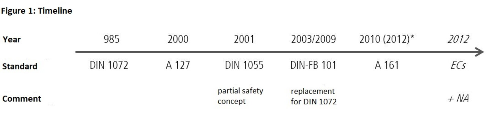
1.4 Timeline
The following illustration shows which standards serve as the basis for the DWA worksheets:
2. Loads from two standards - A comparison
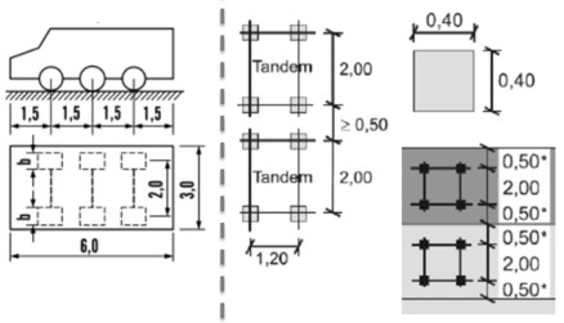
Figure 2 shows a section of Figure 1 of A 127 (left side: SLW 60) and of Figure 4.2 of DIN-FB 101 (right side: LM 1).
In the following, the traffic load is used as the only action. In contrast to structural engineering, the term "live load" has become established as a collective term for variable loads as a load from "real" traffic, whereby "traffic" can mean road, rail or air traffic. The following specifications serve as a guide to the definition commonly used in pipe and manhole construction.
2.1 Area loads
- Infinitely extended, specification e.g. in kN/m²
- no load decrease over the depth, constant value
- no overlaps (these were sensibly already considered in the approach of the area load itself, usually by summing up)
2.2 Single loads
- Limited extension (specification e.g. in kN/m², but spatially limited)
- Load reduction over the depth
- Overlap with neighboring concentrated loads
2.3 Comparison of SLW 60 with LM 1
If the two vehicles are contrasted, some remarkable features stand out.
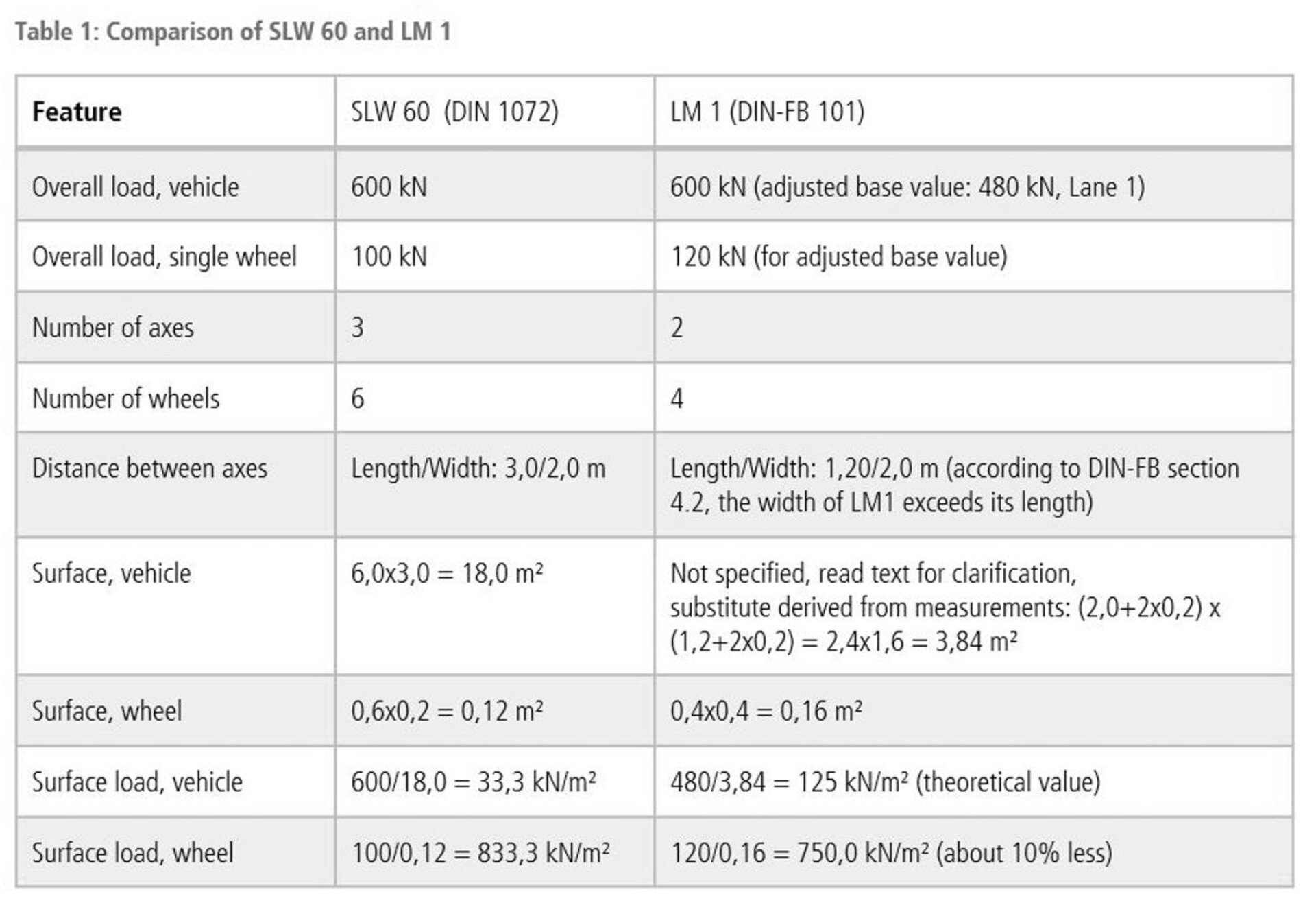
Although the basic values of 600 kN agree in the total load; however, the calculation is carried out in DIN-FB 101 with the adjusted basic value, which reduces the total load. Thus, the load model (LM) 1 is "lighter" than the SLW 60. Since dimensions and load values - both for the consideration of the vehicle and for individual wheels - are different, different area loads (stresses) arise.
For the SLW 60 (àA 127), the regulations contain clear specifications for the gross floor area of the vehicle; these are completely missing in DIN-FB 101 (àA 161). If the outer edges of the wheels of the LM 1 are taken as a basis, the area is calculated as 3.84 m² - which (would) result in significantly higher pressures. The surface loads from the single wheel, on the other hand, agree quite well.
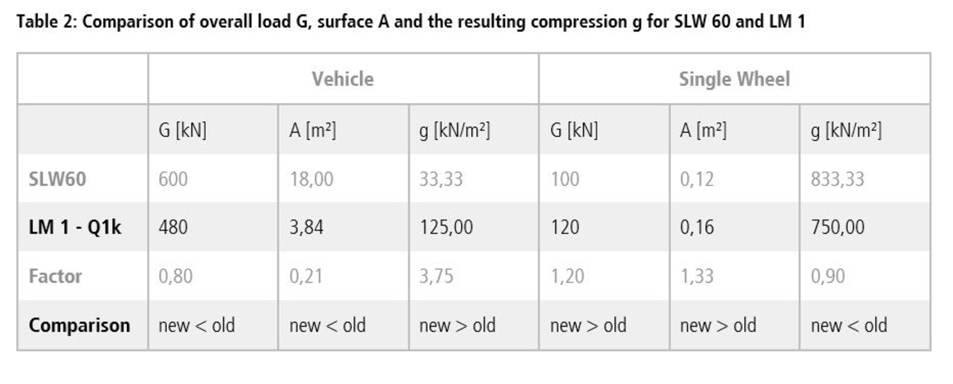
The gross base area of the LM 1 can be determined - purely theoretically! - backwards via the pressures: From the SLW 60 with 600 kN and 18 m², stresses of 33.3 kN/m² result. With the same pressure and an (adjusted) total load of 480 kN, the area of LM 1 is 14.4 m².
It is assumed that this conversion is not in the sense of the standard drafters. It follows from this: The LM 1 - considered as a complete vehicle - has no surface area! Nevertheless, this approach could serve as a solution suitable for everyday use.
2.4 Interim result
The different load models alone are likely to cause deviations when comparing existing calculations with the newer approaches. Impact factors and partial safety factors as well as combination factors for other actions add to the difficulty. The vehicles can only be compared to a limited extent.
3. Soil pressures and load propagation
As a technical report for bridges, DIN-FB 101 has its justification; the regulations it contains are valid for engineering structures, as a bridge undoubtedly is. The depth of action of the effects is geometrically limited by the structure, LM 1 can be reasonably applied.
In the course of standardization, the DIN-FB is also accessed from other sets of rules. When considered in more detail, this approach can lead to problems: The technical report does not always seem to be the appropriate means.
Especially in pipeline and manhole construction, the correct consideration of LM 1 is a challenge. Load propagation angles, overlaps and depth (overburden height) have a significant influence on the design of buried pipes. The basis is Figure 2.
3.1 Distinctions
Simplifying assumptions were made for the following investigations:
- Only the traffic load from load model 1 is considered.
- Area loads are not considered (not even the "uniformly distributed load" on traffic areas: This is constant at e.g. 9 kN/m² for lane 1 and can be added to the existing stress if required, since the area load does not decrease with depth. The A 161 does not inherit the uniformly distributed load of the DIN-FB).
- For simplicity, the load spread is assumed to be less than 2:1, which corresponds to an angle of approx. 63° against the horizontal.
- A possibly existing, load-distributing (road) pavement is not taken into account à propagation over the depth t = 0 m (level of the ground surface, GOK) to the considered depth t = x m is constant.
- The semi-probabilistic safety concept with its different partial safety factors is ignored.
- Other loads such as earth pressure, groundwater or internal pressure of the pipeline are not part of this investigation.
- The main lane under lane (FS) 1 is considered; FS 2 is mentioned separately, if necessary.
This leaves a sole reference to the double-axle itself; this seems suitable to illustrate the principle.
3.2 Observation on the single wheel
The load propagation of a load limited in area - e.g. a wheel load - forms a truncated pyramid with the tip as the top of the pyramid and its projection downward as the base. In the plan view, the base surface at the top ground surface and the edges in the depth can be seen; in the section, a trapezoidal surface is generated.
In the present case of LM 1, the base area of 40x40 cm is square; the projection area defined by the load propagation angle and the depth is also square and increases quadratically, as shown by the following calculation for 120 kN wheel load (half axle load according to LM 1) and a load propagation of 1:2:
- Depth: 0 m Area:0.16 m² Stress: 750 kN/m²
- Depth: 1 m Area:1.96 m² Stress: 61.2 kN/m²
- Depth: 5 m Area:29.16 m² Tension: 4.12 kN/m²
- Depth: 10 m Area:108.16 m² Stress: 1.11 kN/m²
With increasing depth, the soil stress from the wheel load decreases due to increasing edge length of the pyramid base. This distributes the load over a larger area.
3.3 Superposition with a second wheel
Depending on the distance between the concentrated loads, the load propagation angle and the soil properties, the base area of the load at the ground level and the depth considered, the cones of adjacent concentrated loads will overlap. This overlap can be determined mathematically and displayed graphically.
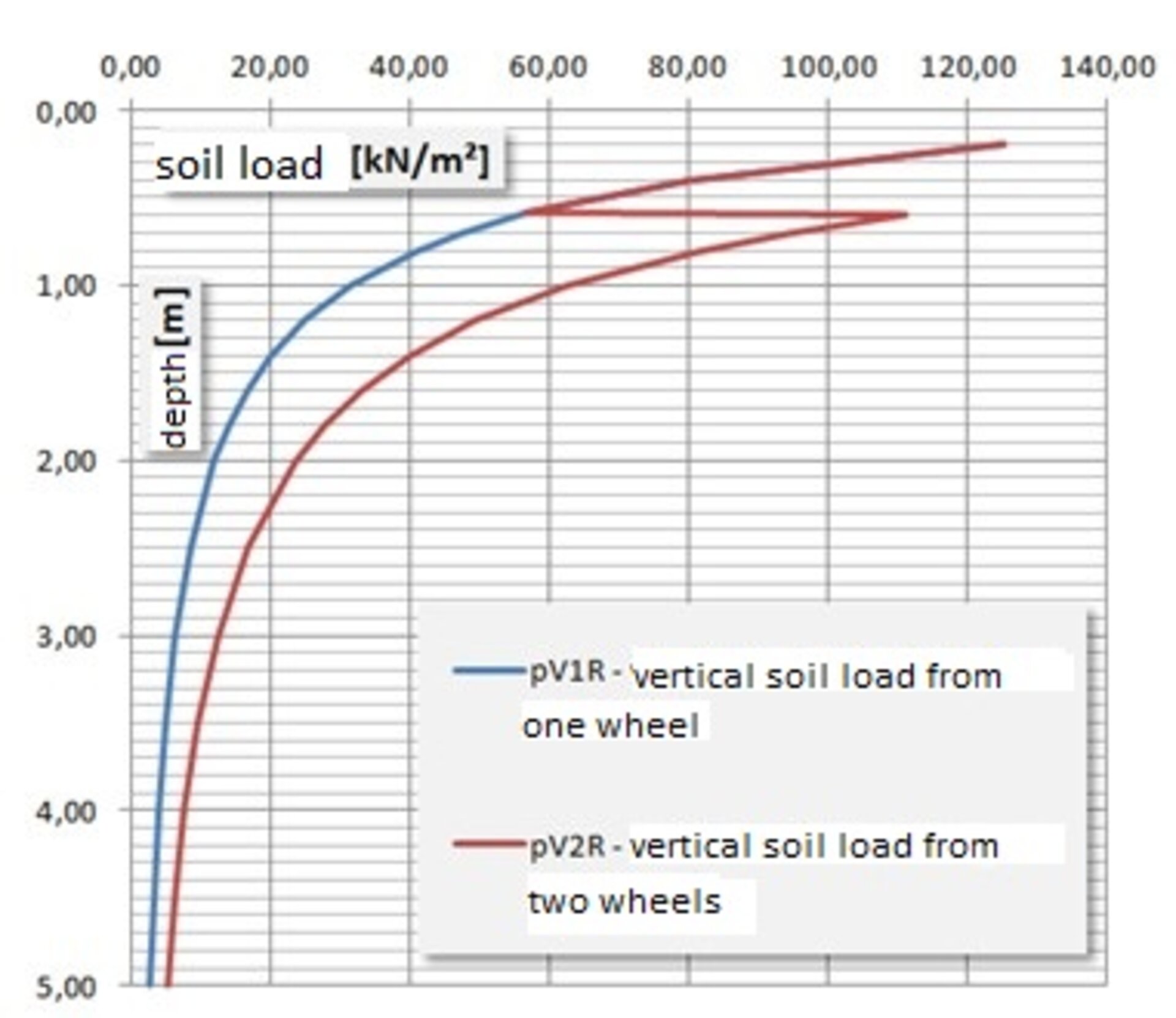
Figure 3 shows a jump from 56.5 kN/m² at t = 0.59 m to 111.1 kN/m² at t = 0.60 m. While at t = 0.59 m the pyramid bases just do not touch each other, at t = 0.60 m there is already contact/overlap. The blue line in the figure represents the course of the undisturbed concentrated load; the red line takes into account the doubling of the stresses.
The single stress, which decreases with increasing depth, grows abruptly due to the overlap, in the case of two equal single loads to double the value. For two wheel loads, the imagination is usually sufficient; if there are three or more loads, which may be offset in the section, graphic aids are required.
3.4 Full overlay of the DIN-FB
The complete load model 1 consists of two lanes with one vehicle each, see Figure 2. Tables and diagrams were created for a lane width of 3.0 m. The overlaps of the load propagation cones are shown in Figure 4.
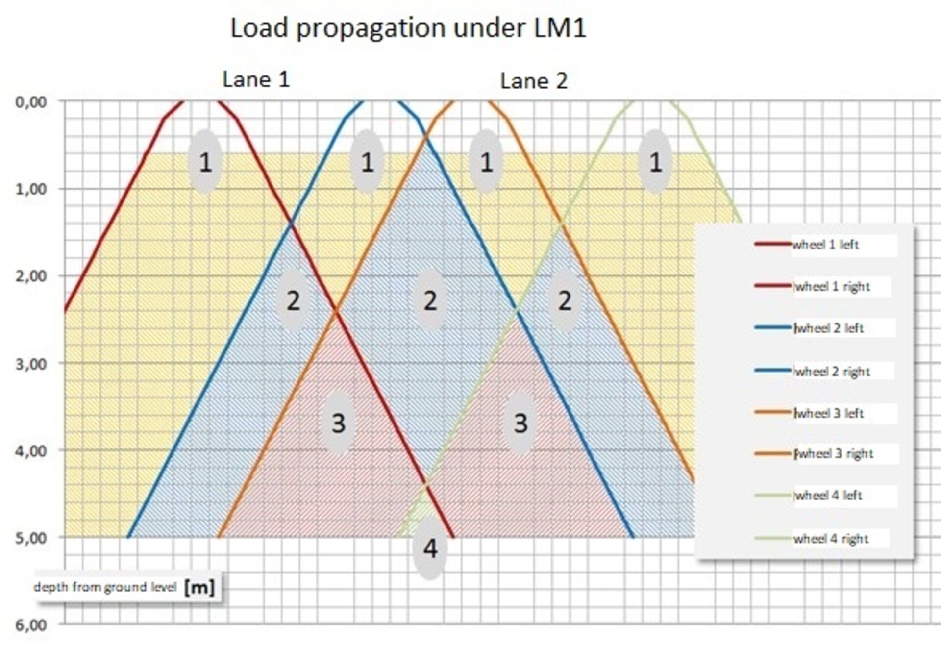
A mental section across both lanes is shown in Figure 4. At the beginning, only one axis of the vehicle is considered. The distances are scaled. In the legend, four individual wheels at the GOK are assigned to the course lines. Numerical values indicate the number of wheels to be considered in this area. The stress jump from Figure 4 occurs at each of these locations.
One-dimensional overlaps occur at depths of 1.40 m, 2.40 m, and 4.40 m. The illustration ends at 5.0 m; as an example, one of four stress values can become decisive here - depending on whether the single wheel load or the superposition of several wheel loads leads to a maximum at the reference depth.
Deviating from the above-mentioned delimitations, Figure 4 is based on a load-distributing pavement with a height of 20 cm (Recommendation A 161). Within the pavement, the spreading is 1:1, below it 1:2. The orange shaded area illustrates the influence of the second vehicle axis: At a depth of 60 cm, a doubling takes place, which can hardly be represented two-dimensionally. Consequently, the numerical values 1-4 can also be doubled: At the boundary of FS 1 and FS 2, eight wheels are to be superimposed.
3.5 Interim result
The comprehensibility of two-dimensional calculations and graphics fails because of the limited display possibilities. It is true that the LM 1 has a regular structure: Distances and dimensions can be mirrored along the longitudinal and transverse axes of the vehicle. However, more in-depth considerations are required:
- Loads on FS 1 and FS 2 are different (120 kN to 80 kN wheel load).
- Complete recalculation required for lane widths < 3 m
- General load patterns for special vehicles with asymmetric body (forklifts, reach stackers, aircraft)
- Spreading in the road surface e.g. below 1:1, below 1:2 or arbitrary, depending on the ground
If non-linear propagations are to be investigated in more detail, it is advisable to use the finite element method (FEM).
4. Future prospects
A comparison of SLW 60 and LM 1 is only possible to a limited extent, as the above comparison shows. Determining soil stresses from LM 1 involves considerable additional work; hand calculations or simple checks are hardly feasible.
The complexity of the subject is enough to fill a master's thesis. It is possible that the recommendation made here to determine the stresses under LM 1 in a simplified way using a substitute area of 14.4 m² will prove successful. The daily application would be served by this.
At present, the only interim solution is to record LM 1 in engineering terms. It is necessary to influence the responsible authorities, committees and working groups in order to obtain a permanently meaningful, comprehensible load approach. It remains to be seen whether DIN-FB 101, which was originally designed for bridges, is equally suitable for shafts and pipelines.
Literature:
[1] DIN 1072: Road and path bridges; load assumptions, December 1985
[2] Worksheet ATV-DVWK-A 127: Structural analysis of sewers and pipelines, August 2000
[3] DIN 1055-100: Actions on structures, part 100: Fundamentals of structural design, safety concept and design rules, March 2001
[4] DIN Technical Report 101: Actions on bridges, March 2009
[5] Worksheet DWA-A 161: Structural analysis of jacking pipes, September 2010