Table of contents
1. Regulations
2. Static calculation according to ATV-DVWK-A 127
3. Structural analysis with FEM
4. Results
5. Summary
Authors: Dipl.-Ing. Vladimir Lacmanović, Dipl.-Ing. Frederik Müller
(This article was originally written in German an translated with Deepl.)
Stability of underground cable ducts in bundles
Electrical cables, fiber optic cables and other sensitive components of modern infrastructure are often laid in protective pipes in the ground. The protective role is usually played by plastic pipes made of polyethylene (PE), polypropylene (PP) or polyvinyl chloride (PVC). The optimum wall thickness required for the cost-effectiveness and stability of these pipes can be determined using static calculations. A special feature here is the dimensioning of several pipes as a package or cable bundle.
1. Regulations
The European standardization codes (EuroCodes, EC) and the German Institute for Standardization (DIN), which are commonly used in the construction industry, lack more precise specifications for underground pipes. In Germany, associations such as
- The German Association for Water, Wastewater and Waste (DWA, formerly: ATV-DVWK)
- The German Technical and Scientific Association for Gas and Water (DVGW)
- The German Society for Trenchless Technology e.V., in short: GSTT
as well as associations that deal with quality assurance, implementation and further training. Some of these associations publish worksheets and information sheets, information and recommendations that have a quasi-normative character for experts. The ATV-DVWK-A 127 worksheet offers a concept for the dimensioning of underground pipes. The regulations are based on the laying of a single pipe in a trench or embankment. In addition to the pipe, the surrounding soil is to be considered as a static system: The soil-pipe system is created.
A relevant element is the system stiffness of this soil-pipe system, which is made up of the geometry and material properties of the pipe as well as soil parameters. Depending on this system rigidity, floor conduit systems are classified as "flexible" or "rigid". The above-mentioned materials commonly used for cable ducts can withstand deformations that are well above the limits of normal building construction. ATV-DVWK-A 127, for example, allows 6% of the pipe diameter for sewers.
Impacts such as earth load or road traffic deform the pipe. The pipe activates the surrounding soil in the lateral area of its transom (3 o'clock and 9 o'clock position) and generates support. In the case of flexible plastic pipes, the surrounding soil bears a significant part of the load. The area of influence of the soil disturbed by a pipe is four pipe outside diameters according to the regulations (1), as shown in Figure 1.
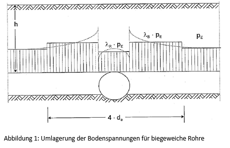
ATV-DVWK-A 127 therefore assumes that an adjacent pipe may only be installed at a distance of 2 x 1.5 = 3 pipe outer diameters. In the case of cable ducts in a bundle, the distances in the horizontal direction are generally much smaller. In addition, cables are laid vertically on top of each other in several layers. A static calculation in accordance with ATV-DVWK-A 127 is only justified as an initial assessment for the problem described, and even common pipe statics programs only allow an approximation at best.
2. Static calculation according to ATV-DVWK-A 127
The calculation module A127 of the pipe statics software IngSoft EasyPipe enables an estimation of the individual pipe. The program maps the equations of the self-contained set of rules; see below for interpretation of the results.
3. Structural analysis with FEM
The modulus of elasticity is required to create a continuum structural analysis. According to ATV-DVWK-A 127, this is the deformation modulus EV or Young's modulus of the soil. The modulus of rigidity ES from a soil expertise must be converted using the Poisson's ratio of the soil. One suggested solution is to use the finite element method (FEM). In this way, the entire pipe package with the surrounding soil can be represented as a continuum model. Using symmetry, if available, it is sufficient to model one half of the cable bundle.
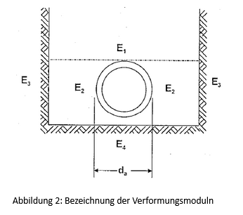
The soil with its deformation moduliEi is divided into four zones for the pipe statics, see Fig. 2. The soil above the pipe is the overburden (E1). The pipe zone (E2) represents the soil adjacent to the pipe - the embedment. The soil to the side of the pipe outside the embedment is the native soil or topsoil (E3). Under the pipe, the soil is often assumed to be stiff, as consolidation is assumed (E4).
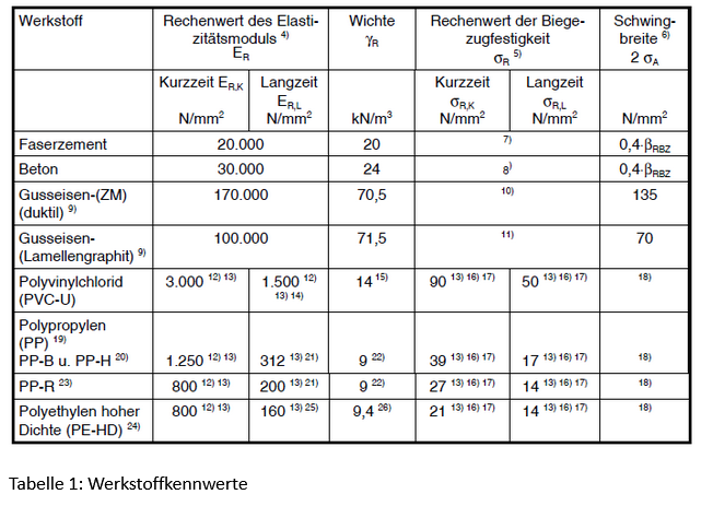
The following project example is intended to illustrate the situation described. Eight pipes are laid next to each other in five rows on top of each other. The pipes have an outer diameter of 160 mm and a wall thickness of 7.7 mm. The horizontal and vertical distance between the pipes is 60 mm. The trench width is selected in accordance with DIN EN 1610. PVC pipes are used for the project. Mechanical properties can be found in the regulations (1), see Table 1.
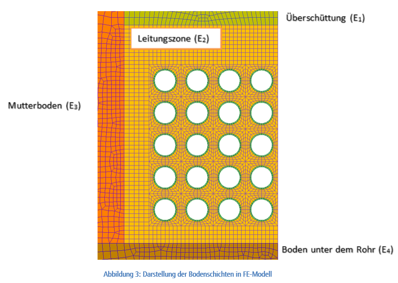
The originally specified soil properties were adjusted depending on the installation and backfill conditions with reference to Table 8 of the ATV-DVWK-A 127 (1) worksheet. For the construction work, it should be mentioned that special attention must be paid to the installation and compaction of the soil between pipes in the bundle. Possible designs include the use of temporarily flowable, self-compacting backfill materials (ZFSV, liquid soil) or concrete encasements. The structural calculations are carried out on the basis of the regulations using the FE method in order to be able to take the installation in the bundle into account, see Fig. 3. The model is symmetrical in relation to the vertical plane between the fourth and fifth column, so that it is sufficient to consider one half of the system. Symmetry is established at the cut edge by appropriate support conditions.
Spatial FE models form the basis for the calculations performed. For the static calculation of the earth and traffic loads (SLW 60), the pipes are discretized using four-node shell elements. The pipe zone, overburden, in-situ soil and the soil under the pipe are discretized using eight-node solid elements. The contact surface between pipe and soil is simulated by a non-linear 3D contact (surface on surface). Only compressive forces are transferred, but no tensile or shear forces. The dead weight loads are determined by gravitational acceleration and assignment of the material-specific weights to the corresponding elements.
The live load is taken into account by placing a distributed load on the model surface. Linear-elastic behavior of the material is assumed (Hooke's law applies). Since this is a stability problem, geometrically non-linear calculations are performed. The long-term characteristic values of the pipe material are used as the basis for the verification.
4. Results
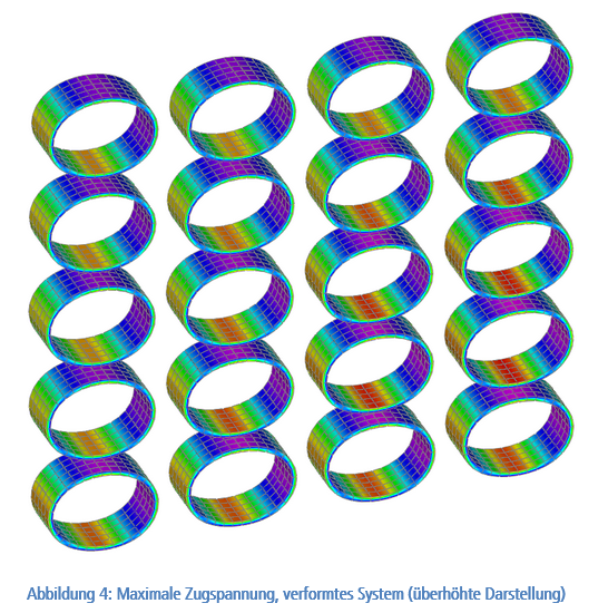
The ATV-DVWK-A 127 worksheet is based on a global safety concept. For PVC pipes, the required safety against stress and stability failure is γ = 2.5. To assess the stability and serviceability of a pipeline, its stresses, deformations and stability must be investigated. When interpreting the results, it should be noted that the equations of worksheet A 127 apply to a single pipe with symmetrical installation - whereas the FEM approach takes into account the real asymmetry of the pipe bundle. Figure 4 shows that the pipes deform differently and exhibit different stress curves.
The calculation results in detail are
1. stresses: The stresses determined with the empirical formulas of ATV-DVWK-A 127 are higher than those of the FE calculation and therefore provide a lower level of safety.
2. deformations: The deformations calculated according to ATV-DVWK-A 127 are also higher than those of the FE calculation and therefore provide a smaller safety.
3. stability: The safety against stability failure according to A 127 is higher than calculated by FEM. This results in a supposedly higher level of safety.
The stability failure becomes decisive. However, the ATV-DVWK-A 127 worksheet assumes a symmetrically bedded pipe. In contrast, installation as a cable bundle results in uneven embedment.
5. Summary
The ATV-DVWK-A 127 worksheet is suitable for the structural analysis of individual pipes. Application to several pipes, cable bundles or pipe packages is not recommended: The above example shows that the decisive stability verification overestimates the stability of the system. The FE calculation is more realistic, as it captures the system stiffness of the floor-pipe system more accurately and takes into account the asymmetry of the cable bundle.
Literature
(1) ATV-DVWK Worksheet A 127: Static calculation of sewers and pipes (2000-08)
(2) IngSoft EasyPipe Version 2.8.5.6
(3) NX Nastran - User Manual
(4) Femap - User Manual